Class Diagrams: Structure of Objects, Attributes, Methods
Introduction
A class diagram is one of the most commonly used diagrams in the Unified Modeling Language (UML). It provides a static view of a system, showing the classes, their attributes, methods, and the relationships between them.
For system design interviews and object-oriented programming (OOP) practice, class diagrams are invaluable in modeling the blueprint of a system before coding.
Purpose of Class Diagrams
- Represent the structure of a system at the class level.
- Define attributes (data) and methods (behavior) of classes.
- Show relationships (associations, inheritance, dependencies).
- Help in design discussions and interviews to communicate ideas clearly.
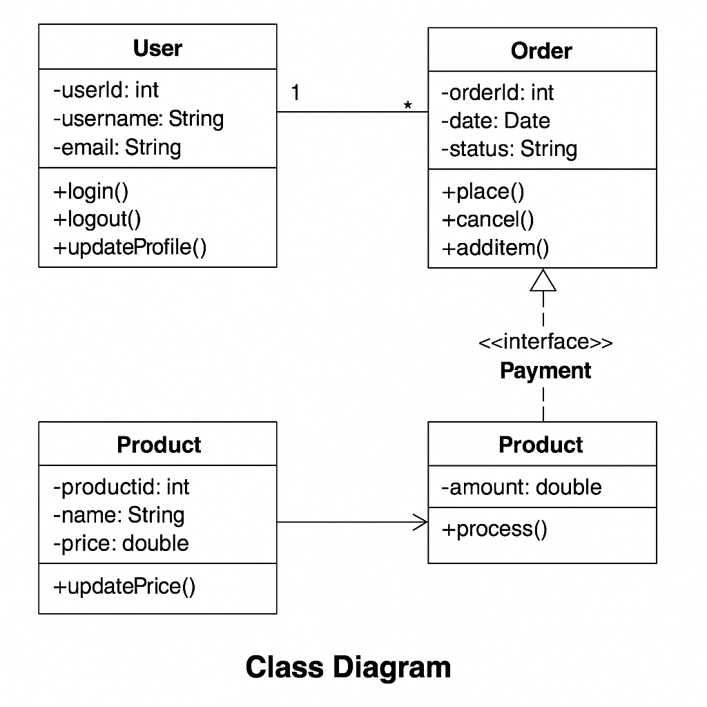
Elements of a Class Diagram
A class diagram is typically represented as a rectangle divided into three sections:
+-------------------------+
| Class Name              |
+-------------------------+
| Attributes              |
+-------------------------+
| Methods                 |
+-------------------------+
1. Class Name
- The name of the class (e.g.,
User,Order). - Abstract classes are written in italics.
- Interfaces are prefixed with
<<interface>>.
2. Attributes (Fields)
- Represent the state/data of a class.
- Example:
username: String,balance: double.
3. Methods (Operations)
- Represent the behavior or functions.
- Example:
login(),withdraw(amount: double).
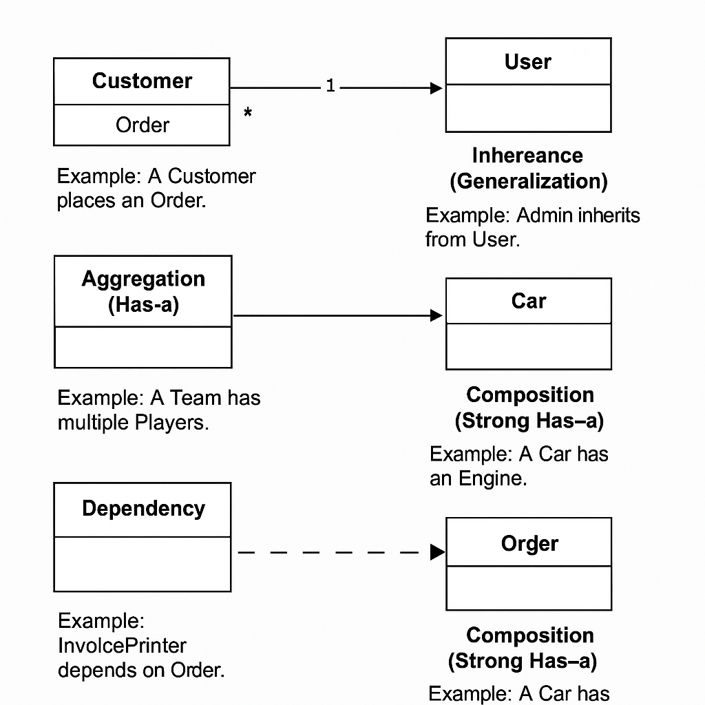
Relationships in Class Diagrams
Class diagrams also capture how classes relate to each other:
Association (line)
- Shows a relationship between two classes.
- Example: A
Customerplaces anOrder.
Multiplicity
- Defines how many objects can participate in a relationship.
- Example:
1 Customer↔* Orders.
Inheritance (Generalization)
- Arrow with hollow triangle.
- Example:
Admininherits fromUser.
Aggregation (Has-a, Hollow Diamond)
- Whole–part relationship.
- Example: A
Teamhas multiplePlayers.
Composition (Strong Has-a, Filled Diamond)
- Stronger form of aggregation. If the container is destroyed, the parts are too.
- Example: A
Carhas anEngine.
Dependency (Dashed Arrow)
- A class depends on another but not permanently.
- Example:
InvoicePrinterdepends onOrder.
Example: E-Commerce System
Let’s model a simplified e-commerce system with UML class diagrams.
+-------------------+          +-------------------+
| Customer          |          | Order             |
+-------------------+          +-------------------+
| id: int           |<>--------| orderId: int      |
| name: String      | 1    *   | date: Date        |
+-------------------+          +-------------------+
| placeOrder()      |          | calculateTotal()  |
+-------------------+          +-------------------+

          ^
          |
   +-------------+
   | PremiumCust |
   +-------------+
   | loyaltyPts: int |
   +-----------------+
   | redeemPoints()  |
   +-----------------+
Explanation
Customerplaces manyOrders(1-to-many association with aggregation).PremiumCustomerinherits fromCustomer.- Methods like
placeOrder()andcalculateTotal()are included.
Class Diagrams in Interviews
System design interviews may involve creating or interpreting class diagrams:
- “Design a library management system” → Classes:
Book,Member,Loan. - “Design a ride-hailing service” → Classes:
Rider,Driver,Trip.
Showing clear class diagrams can improve communication and demonstrate design clarity.
Best Practices
- Keep diagrams simple; don’t overload them with unnecessary details.
- Show core entities and their relationships.
- Use multiplicity (1, *, 0..1) where relevant.
- Highlight inheritance and composition clearly.
- Use diagrams as a discussion tool, not just documentation.
Conclusion
Class diagrams are the backbone of UML modeling, capturing the static structure of a system. By understanding classes, attributes, methods, and relationships, you can effectively communicate designs in interviews and real-world projects.
They serve as a bridge between requirements and code, making them essential in both academic and professional contexts.